Line Following Robot
Project Overview
This project involved creating a two-wheeled autonomous robot that follows a track made of tape laid out on the floor. We designed and fabricated a custom mechanical chassis using 3D printing, developed a closed-loop controller running on Arduino, and integrated IR reflectance sensors to ensure accurate line tracking. The system also features real-time user control through serial commands, allowing for testing and adjustments without recompiling code.
The robot uses a strict line-following approach with two IR sensors positioned to fully cover the line width. The control logic continuously adjusts the robot's position based on sensor readings, ensuring it stays centered on the track. When both sensors detect the line, the robot moves straight; when one sensor detects a darker surface, the robot turns accordingly. If the line is lost completely, the robot pivots until it reacquires the track.
Project Gallery
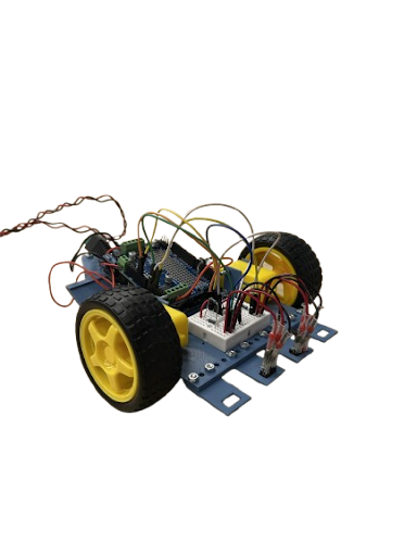
Assembled robot on track
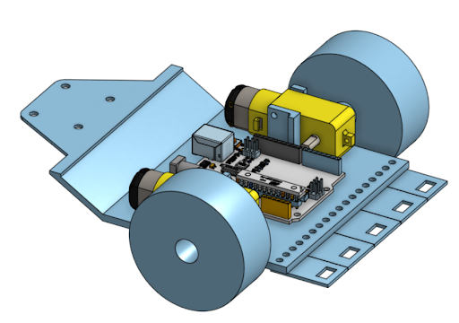
3D printed chassis CAD model
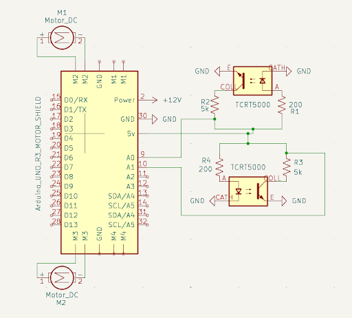
Circuit wiring and connections
The Challenge
The original chassis had unstable laser-cut motor mounts and was positioned too high above the ground, affecting stability and precision. The robot needed to accurately detect and follow the line while maintaining smooth, responsive control. Additionally, we needed a way to test and adjust parameters in real-time without constantly recompiling the code.
The Solution
We designed a custom 3D-printed chassis with sandwiched motor mounts for stability, a lower center of gravity, and adjustable sensor mounts for testing different configurations. Implemented a robust line-following algorithm with turn and pivot modes. Added serial command functionality allowing real-time speed adjustments, manual control, and mode switching without code recompilation.
Technical Implementation
Hardware Components
- Arduino Uno microcontroller
- Adafruit Motor Shield
- Two DC gearmotors with wheels
- IR reflectance sensors (TRCT5000)
- 3D-printed chassis
- Caster wheel
- 12V power supply
Software Features
- Autonomous line following
- Real-time serial commands
- Adjustable speed control (0-255)
- Manual forward/backward control
- Auto/manual mode switching
- Line recovery (pivot mode)
- Live sensor data streaming
Key Challenges
- Chassis stability and durability
- IR sensor calibration
- Motor speed tuning
- Line detection accuracy
- Real-time control interface
- 3D print optimization
Technologies Used
- C++ (Arduino IDE)
- Adafruit Motor Shield library
- CAD (SolidWorks/Fusion 360)
- FDM 3D printing
- KiCad (circuit design)
- MATLAB (data visualization)
Mechanical Design
Although we were provided with an initial chassis, we identified critical flaws including unstable laser-cut motor mounts and excessive height above the ground. We designed and fabricated a completely new chassis using 3D printing with three key improvements: lower center of gravity for enhanced stability, sandwiched motor mounts to eliminate play and slack in the wheels, and adjustable sensor mounts allowing us to test different heights and sensor configurations.
The chassis consists of three main components: the caster wheel mount with a sloped design for structural support, the gearmotor mounts with an L-shaped inner structure to prevent snapping under external forces, and the modular IR sensor mounts that can be repositioned using screws and nuts. The motors are spaced 2.625 inches apart to accommodate the Arduino in the center, and all components are designed to maintain the robot parallel to the ground for optimal sensor performance.
Sensor Calibration & Circuit Design
We calibrated the IR sensors by collecting readings from both white tape and dark surfaces. The white surface produced readings around 60, while the dark surface produced readings around 750. To account for variations in lighting and surface texture, we set the threshold at 80, providing tolerance for worn or inconsistent tape sections.
The circuit design centered on determining the optimal R_Sense resistor value for the TRCT5000 IR sensors. Based on the datasheet showing an emitter current of approximately 1 mA and using Ohm's Law with the 5V supply voltage, we calculated the required resistor value as 5 kΩ. The complete circuit was designed in KiCad, integrating the IR sensors with the Adafruit Motor Shield and 12V power supply for the motors.
Control Logic & Algorithm
The line-following algorithm implements a strict approach with four main scenarios: When both sensors detect white (the line), the robot moves straight at base speed. If the left sensor detects a darker surface, the robot turns right by reducing the right motor speed. If the right sensor detects darker, it turns left by reducing the left motor speed. When both sensors lose the line, the robot enters pivot mode, rotating in place until it reacquires the track.
We implemented three distinct speed settings: base speed (40) for straight movement, turn speed (35) for gentle corrections, and pivot speed (30) for line recovery. The system continuously monitors sensor readings and adjusts motor speeds accordingly, with the slower motor determining the turn direction. This approach ensures smooth, responsive tracking while maintaining stability.
Real-Time Serial Control
To facilitate testing and debugging, we implemented a comprehensive serial command interface. Users can send commands through the Arduino Serial Monitor to control the robot in real-time without recompiling code. Available commands include "stop" to halt all movement, "resume" to return to autonomous mode, "speed <0-255>" to adjust the base speed, "forward" and "backward" for manual one-second movements, and "auto" to switch back to line-following mode.
The system continuously streams live data to the serial monitor, displaying IR sensor readings, current state (turning left/right, going straight, or lost line), and motor speeds and directions for both wheels. This real-time feedback proved invaluable for tuning the control parameters and understanding the robot's behavior during operation.
Results & Data Visualization
We created MATLAB plots to visualize the robot's performance during runs, showing IR sensor readings and motor outputs over time. The plots clearly illustrate how the robot perceived and reacted to different sections of the track. Flat regions in the motor voltage correspond to straight sections where no corrections were needed, while fluctuations indicate turns or adjustments. This visualization provided valuable insights into the control system's performance and helped identify areas for optimization.
The robot successfully completed the track with smooth, consistent line following. The combination of properly calibrated sensors, tuned motor speeds, and robust control logic resulted in reliable autonomous navigation. The real-time control interface proved essential for rapid iteration and parameter tuning during development.
Video Demonstrations
Watch the robot in action! The first video shows the line-following system autonomously navigating the track, while the second demonstrates the real-time serial control interface allowing manual commands and parameter adjustments.
Line Following in Action
Serial Control Interface
Reflections & Future Improvements
The project was completed successfully with good pacing and effective teamwork. Each team member focused on different aspects while maintaining strong communication. However, we identified several areas for improvement. The gearmotor mount was too thin and eventually snapped, indicating a need for reinforcement in high-stress areas. We also didn't fully consider 3D printing orientation, resulting in excessive support material usage.
Future improvements would include adding more IR sensors in an arc configuration to increase detection range and precision, allowing earlier line detection and more accurate responses. The robot's speed and accuracy could be enhanced through better sensor placement and refined control algorithms. Additionally, working together more simultaneously rather than individually would improve coordination and consistency in future projects.