3D Scanner
Project Overview
For this project, we created a 3D scanner using an IR distance sensor and two servos to create a pan-tilt mechanism. The system uses an Arduino Uno to collect distance measurements and passes the data to a MATLAB script to create a 2D representation of the scanned object. The project successfully integrates mechanical design, electrical engineering, and software development to produce accurate scans of physical objects.
The scanner works by sweeping an IR sensor across both vertical and horizontal axes, collecting distance measurements at each point. The vertical servo scans from top to bottom while the horizontal servo rotates to capture different angles. This systematic approach creates a grid of distance values that can be visualized as a heat map, revealing the shape and contours of the scanned object.
Project Gallery
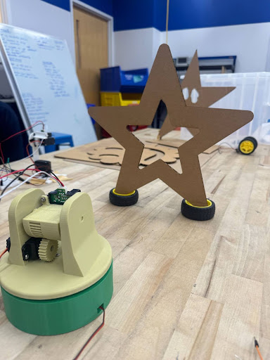
Scanner apparatus with star object
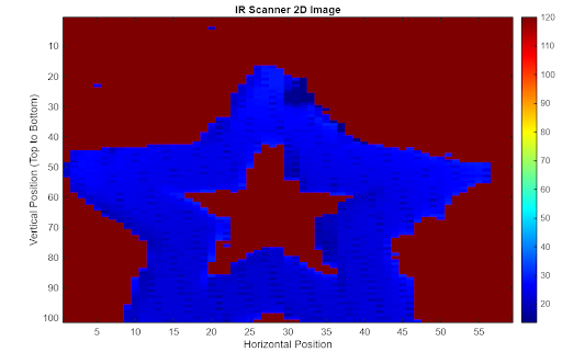
MATLAB visualization of scanned star
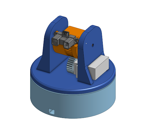
3D CAD model of scanner mechanism
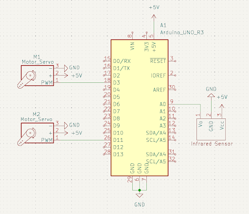
Circuit diagram and wiring
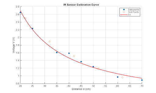
IR sensor calibration curve
The Challenge
Creating a stable mechanical system that could accurately position the IR sensor while minimizing wobble and vibration. The electrical connections needed to be robust enough to handle continuous servo movement without disconnecting. Additionally, calibrating the IR sensor to provide accurate distance measurements across the scanning range was critical for quality results.
The Solution
Designed a custom 3D-printed apparatus with a low center of gravity using a rack-and-pinion mechanism for smooth tilting. Implemented a comprehensive sensor calibration process using voltage-to-distance curve fitting in MATLAB. Developed Arduino code with precise timing controls and CSV data formatting for seamless integration with MATLAB visualization.
Technical Implementation
Hardware Components
- Arduino Uno microcontroller
- IR distance sensor (Sharp GP2Y0A21YK)
- Two servo motors (pan and tilt)
- 3D-printed mounting apparatus
- Rack-and-pinion mechanism
- 5V power supply
Software Features
- Automated 2-axis scanning
- Real-time distance measurement
- CSV data output format
- MATLAB visualization
- Sensor calibration algorithm
- Distance thresholding
Key Challenges
- Mechanical stability and wobble reduction
- Wire management during movement
- IR sensor calibration accuracy
- Serial data transfer reliability
- Angular distortion compensation
Technologies Used
- C++ (Arduino IDE)
- MATLAB (data visualization)
- FDM 3D printing
- Servo.h library
- Analog sensor interfacing
Mechanical Design
The mechanical apparatus was designed with stability as the primary concern. We mounted two servos together using a combination of 3D-printed parts and bolts, keeping the center of gravity as low as possible to minimize sway during scanning. The base servo handles horizontal panning, while a second servo mounted on the underside of the panning plate provides vertical tilt.
Rather than directly mounting the tilt servo, we implemented a rack-and-pinion mechanism where a gear on the servo horn meshes with teeth on the tilt plate. This design allows for smooth, controlled tilting of the sensor while maintaining a compact and stable form factor. The entire apparatus was fabricated using FDM 3D printing and consists of five interlocking parts secured with screws.
Sensor Calibration
Accurate distance measurements required careful calibration of the IR sensor. We collected voltage readings at known distances ranging from 20cm to 70cm, avoiding the sensor's peak response region below 20cm as indicated in the manufacturer's documentation. Using MATLAB curve fitting, we derived the calibration equation: d = 49.3511 / (V - 0.2317), where d is distance in centimeters and V is voltage.
To validate the calibration, we tested the equation with additional data points and calculated the error. The largest errors occurred at distances beyond 60cm, which were outside our typical scanning range. We implemented distance thresholding in the Arduino code to filter out readings beyond 40cm, labeling them as "no object detected" with a value of 120cm for consistent visualization.
Scanning Process & Results
The scanning algorithm operates in three coordinated steps: First, the vertical servo sweeps from top to bottom (0° to 90°) while the IR sensor continuously captures distance measurements. Second, these measurements are streamed to the serial monitor in CSV format, with each vertical sweep creating a new data row. Third, once a vertical scan completes, the horizontal servo rotates one degree and the process repeats.
We tested the scanner on a star-shaped object and achieved excellent results. The MATLAB visualization using the imagesc() function clearly showed the object's shape, including the characteristic gap in the center. The scan accurately captured both the scale and geometry of the original object, with only minimal angular distortion. The 150ms delay between servo movements provided an optimal balance between scan speed and data quality.
Reflections & Future Improvements
The project successfully demonstrated the integration of mechanical, electrical, and software systems to create a functional 3D scanner. We're particularly proud of the stable mechanical design and the accuracy of our sensor calibration. The rack-and-pinion mechanism proved to be an effective solution for smooth, wobble-free scanning.
Future improvements would include better cable management using crimp pins or housings to prevent wire disconnections during operation. Implementing direct CSV file saving rather than relying on serial monitor copy-paste would make the workflow more robust. Additionally, accounting for angular distortion in the MATLAB processing could further improve scan accuracy, and increasing the data point density would yield even clearer images.
Code & Documentation
The complete Arduino code and MATLAB visualization scripts are available on GitHub. The repository includes the calibration code, scanning algorithm, and data processing scripts. You can also download the full project report PDF for detailed technical documentation.